|
The MLS 608 D Series uses floating point DSP technology,
processing data using a combination of 32- and With floating point DSP, it is difficult to clip the audio signal after the ADC and before the DAC (within the DSP audio signal chain). It is important that the audio signal is not clipped at the input ADC. Clipping gives audibly undesirable results and when the audio is clipped at the input, there is no remedy further down the signal chain. If audio clipping occurs at the output DAC and is not a result of clipping at the input ADC, there are ways that clipping can be addressed in the DSP audio signal chain. The meters in DSP Configurator indicate clipping at a user-definable point, with the default setting at -1 dB. This means that the meter indicates clipping when it reaches -1 dBFS, which is 1 dB below actual clipping. Setting the clipping meter below actual clipping provides a safety net to let you know to pull back on input gain before clipping occurs. To increase or decrease the clipping meter indicator:
Meters within DSP Configurator are peak-type meters, referenced to full scale, or 0 dBFS. For the MLS 608 D Series, 0 dBFS corresponds to +21 dBu, which is the maximum output level of the device. Input meters are post-ADC, while output meters are pre-DAC. |
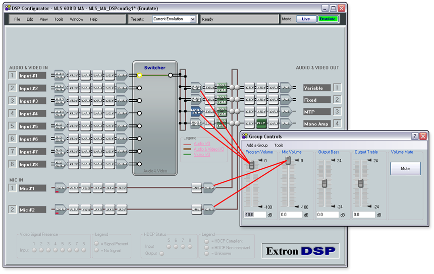
About Setting Gain StructureIn the MLS 608 D Series, the default control point for program volume is the post-switcher gain, while the default control point for microphone volume is the pre-mixer gain. For both program volume and mic volume, a group master control has been preconfigured to create a single point of control for the post-switcher gain points and the pre-mixer gain points, respectively. The front panel volume controls are tied to these group master controls. The front panel volume rotary encoders are linked to these preconfigured group master controls, such that adjusting the position of the front panel encoders will adjust the level of the corresponding group master.
|
Setting Line Input GainFloating point DSP technology is internally more flexible than fixed point. However, an ADC and DAC always run as fixed point, so it is important to optimize the audio by setting the input level to as close to 0 dBFS as possible without clipping. This maintains the bit resolution at 24-bit, and therefore the full dynamic range of the device. Within the DSP, it is not critical to maintain audio levels at 0 dBFS in order to secure the bit resolution at 24-bit. A convenient way to set input gain is to use the building blocks feature. This will give you a gain setting for a particular line level device, designed to give you a nominal operating level. Additionally, a building block can load other processing options such as bass and treble tone control and compression for level normalization and system protection. See the Building Blocks section for more information. You can set the input gain using:
If you are using program material: Set the input level so that the meters reach approximately -15 dBFS to -12 dBFS, with peaks at approximately -6 dBFS. This setting provides enough headroom to accommodate transients or unanticipated loud events in the program material in order to avoid possible clipping. If you are using pink noise:
|
Setting Output Levels (Non-amplified Outputs)In order to set up a gain structure to include signal
processing, you may need to listen as you proceed. At some point in setting
output gain structure, volume may be excessive
|
![]()
Setting Mic Input and Mix LevelsThe default level for the microphone input is 0 dB, unmuted. Muting the input before plugging in a microphone and especially before turning on phantom power is recommended. A convenient way to set mic input gain is to use the building blocks feature. This will give you a gain setting for a specific microphone type, brand and model, designed to bring the mic to a nominal level, turning on phantom power if the mic requires it. Additionally, a building block can load other processing options such as bass and treble tone control and compression for level normalization and system protection. See the Building Blocks section for more information. In this example, the mic/line input 1 signal is set to output 1.
Voice levels at microphone inputs can vary significantly. By having the meters average -20 dBFS to -15 dBFS, there is enough headroom to accommodate sudden changes to voice levels. Further adjustment may be necessary. |
Adjusting Pre-switcher TrimAfter you set the input gain for all line level sources, add any processors that you want to use into the input signal chain (see the Inserting and Deleting a Processor section). You can use the pre-switcher trim control to compensate for any level changes that result from added processing.
To start adjusting the pre-switcher trim:
|
Inserting Output Channel ProcessingAdd any processors that you want to use in the output signal chain. A convenient way to add output channel processing is to use the building blocks feature. This will add room EQ for a number of commonly used Extron speakers, plus a limiter for system protection. See the Building Blocks section for more information.
After you add processors to the output signal chain, the output volume level may clip when set to 100 percent (or less). Floating point DSP allows you to overcome clipping by lowering either the post-switcher gain or the output volume setting. Unless you prevent user controls from changing the volume setting to 100 percent (or to a position where clipping occurs), it is best to:
To prevent user controls from changing the volume to a level where clipping occurs, use soft limits on a group master (see the Group Masters section). Alternatively, you can use the post-switcher gain controls to adjust the output volume. Post-switcher gain controls provide 12 dB of gain, so it is advised that you use a group master with soft limits to control the level with an upper limit of 0 dB or less. Mix levels will also contribute to possible clipping at the outputs and may need to be lowered to maintain the balance between program material (line outputs) and voice. |
Adjusting Post-switcher GainAt this point, setting up gain structure may become a bit of a balancing act. This subsection and the Setting Volume Control for the Amplifier Stage subsection below provide some guidelines, but you may need to go back and forth to set levels optimally. For example, you can control the output level and maintain the level below clipping by using a compressor or limiter in the output DYN (dynamics) block. However, adjusting the post-matrix gain affects how the compressor or limiter works.
When using the post-switcher gain for output volume control, the procedure may be reversed.
|
Setting Volume Control for the Amplifier StageThe amplifiers inputs on the MLS 608 D MA and SA models are set to accept maximum output from the audio signal path. This means that you can set the output Volume control to 100 percent output, with the signal approaching 0 dBFS on the output meter. If 100 percent output volume results in a volume level that is too high for your application, it is recommended that a soft limit is placed on the volume control. A soft limit can be used to prevent the volume control from going above (or below) a selected point. Soft limits are a component of the group master controls. The default group masters for program volume and mic volume are described in the Group Masters section, as well as instructions for applying soft limits. |
![]()
 button beside the