
|
The Advanced Configuration tab is present if a System 5 IP or MediaLink Controller (MLC), or one of their control ports has been selected in the IP Link Tree window. The Advanced Configuration tab varies slightly depending on which product is selected, and has the following functions: Details for each function are provided below. Differences between the System 5 IP and MLC screens are identified. |
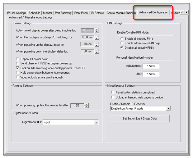
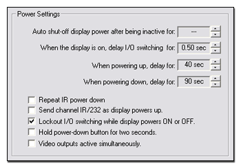
Power SettingsSystem 5 IPMediaLink Controller (MLC)The Power Settings fields are typically populated by the selected device driver, but are user-selectable (adjustable) as described below.
|
|
System 5 IP only
|
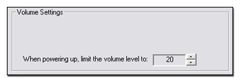
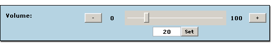
Volume SettingsSystem 5 IP
|
|
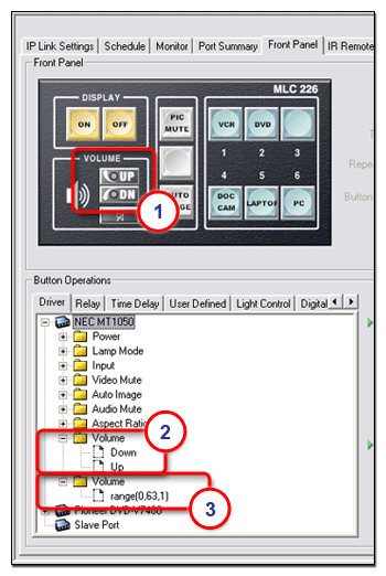
Volume SettingsMediaLink Controller (MLC)There are two types of device driver options available for the volume adjustment on a MediaLink (MLC) device:
|
|
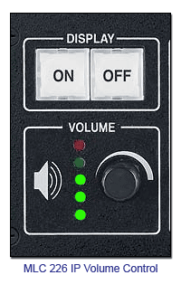
If you configure the Front Panel Volume UP and DOWN buttons (1) in GC with the Volume Up / Down driver (2), the volume control on the MLC front panel will interface electronically with the device like up and down buttons. If you configure the Front Panel Volume UP and DOWN buttons (1) with the Volume range driver (3) the volume control on the MLC front panel will interface electronically with the device like a volume slider. If you choose the Up / Down driver in the Front Panel > Button Operations window, you must also choose the Increment / Decrement option in the Advanced Configuration tab Volume Settings dialog box (see below right). If you choose the range driver in the Front Panel > Button Operations window, you must also choose the Range option in the Advanced Configuration tab Volume Settings dialog box (see below right).
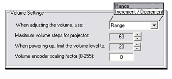
When adjusting the volume, use: Range or Increment/Decrement - Volume control for a projector, display, or audio output device involves one of two methods: selecting a setting within a specific range of values, or sending a simple command to increment or decrement the volume by a fixed amount. Select the appropriate method for the equipment you are using. Refer to the user's manual for the display or audio device. |
|
|
When you choose the Range setting, the Maximum volume steps for projector field becomes active. This field is initially populated by the device driver with the maximum number of volume steps available for the associated projector. If you wish to limit the maximum volume level of the projector, simply adjust this number down to the desired level. You may only lower the maximum volume number. You may not raise this number above the initial setting provided by the associated device driver. |
|
|
The volume control indicator lights on the MLC act in the following manner, depending on the setting of the When adjusting the volume, use field:
|
|
|
The other fields on the MLC Volume Settings dialog box are: |
|
|
|
This feature addresses a problem that occurs with some projectors that use a range type volume control. When the MLC�s knob controls projector volume, sometimes the MLC sends the volume commands faster than the projector can detect and process them. The projector does not detect some of the volume change commands, resulting in a choppy volume ramp. Encoder scaling gives the programmer the ability to slow the knob down to a speed the projector can handle. The drawback is that users must turn the knob more times to change from minimum to maximum volume. It is up to the user to find a balance between smooth audio ramping and the number of knob turns needed to cover the volume range. This requires trial and error for each projector exhibiting this problem. Although this feature is mainly for range type volume control, it applies to any range type command programmed to be executed by the volume knob. |
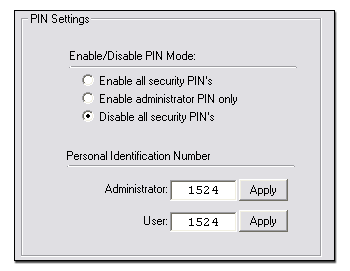
PIN SettingsSystem 5 IPMediaLink Controller (MLC)The Pin Settings dialog allows users to enable/disable the requirement to enter a PIN prior to accessing the device front panel buttons. The options are:
|
|
Note: The factory default PINs are:
Note: See the respective User's Manual for instructions on how to enter a PIN on the device front panel. | |||||||||||||||||||||
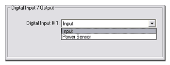
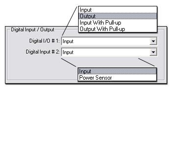
Digital Input / OutputSystem 5 IP
Note: Use the Schedule and Monitor tabs to select conditions, actions, and emails in response to the Input or Power Sensor signal. |
|
Digital Input / OutputMediaLink Controller (MLC)
|
|
Note: Use the Schedule and Monitor tabs to select test conditions, actions, and emails in response to an Input, Input With Pull-up, or the Power Sensor signal. Note: Use the Schedule and Monitor tabs to select the appropriate port, and action or email to be associated with an Output, or Output With Pull-up signal. |
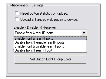
Miscellaneous SettingsSystem 5 IPMediaLink Controller (MLC)
Miscellaneous Settings include:
|
|
The System Status Page is displayed.
The "enhanced web pages" are launched.
|
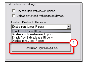
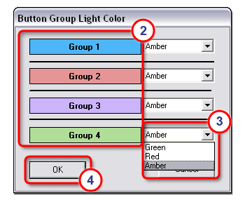
Set Button Light Group ColorIf you have assigned button groups on the Front Panel tab, you can assign different colors for the buttons in each grouping. The color options are:
To assign a color to a specified button group:
When you have assigned multiple buttons to a grouping, only one of the buttons can be activated at a time. When you assign a color to a button group the activated button will illuminate with the assigned color on the physical front panel of the device and in the representation of the front panel in the GlobalViewer interface. Note: On a System 5 IP device only the front panel ROOM buttons can configured in groups. |
|
![]()