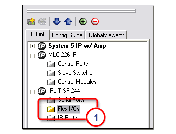
Flex I/O PortsFlex I/O ports are found on the following devices:
Flex I/O ports can be configured in three different ways:
Flex I/O ports allow
IP Link Analog inputs to Flex I/O portsFlex I/O ports can be configured to receive analog voltages for use with photo sensors, level feedback, strain gauges, thermocouples, variable potentiometers and other devices. Incoming analog voltages from 0 to 24 volts are sampled with 12-bit precision. For example, a thermal sensor installed in an equipment rack can be connected to one of the Flex I/O inputs, and the IP Link device can be configured to send an e-mail message, turn on auxiliary cooling fans and turn off equipment if the rack temperature exceeds a specified temperature value. Digital inputs to Flex I/O portsConfigured as digital inputs, the Flex I/O ports can connect to switches, motion sensors, moisture sensors and tally feedback. This provides the ability to receive status from a variety of devices including projector lifts, motorized projection screens, room partition switches, and pushbuttons. Digital outputs from Flex I/O portsWhen configured as digital outputs, the Flex I/O ports can drive LEDs, 24 volt incandescent lamps, an additional external power supply, or other devices that accept a TTL input signal. For applications that require contact closure control, the Flex I/O ports can interface with an Extron IPA T RLY4 (an IP Link accessory featuring four isolated relays). |

![]()
|
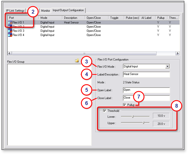
To configure a Flex I/O port:
|
|
|