Modifying Filter Parameters
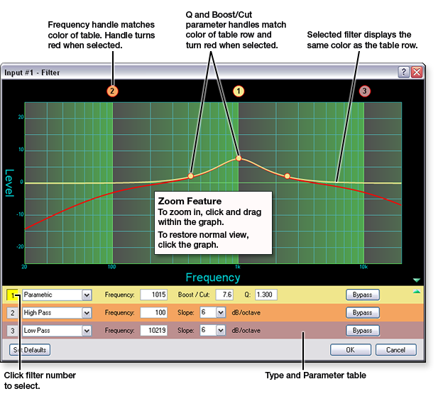
The graph in the Filter dialog box displays the composite
curve of all unbypassed filters, which is indicated by a red line. To
select an individual filter for editing, click the filter number to the
left of the Filter
Selection drop-down list or click the frequency handle. When
selected, the individual filter curve is shown independent of the composite
curve and in the same color as the filter row in the type and parameter
table. See the image below for more details about the graph.
Bypassed filters do not appear in the filter composite.
However, when selected, a bypassed filter appears as a dotted line independent
of the composite curve.
To modify frequency:
Double-click
the FILT
block for an inserted filter. The Filter dialog box opens. Select
the filter that you want to modify. To do so, either click the filter
number to the left of the filter type or click the frequency parameter
handle above the graph (see the image above). Click
and drag the frequency parameter handle left or right to the desired position
or value.
To modify boost/cut:
Double-click the FILT
block for an inserted filter. The Filter dialog box opens. Select
the filter that you want to modify. To do so, either click the filter
number to the left of the filter type or click the frequency parameter
handle above the graph (see the image above). Click
and hold the boost/cut handle in the graph, located at the center frequency.
Drag
the boost/cut handle up or down to the desired position or value.
To modify Q (bandwidth):
Double-click the FILT
block for an inserted filter. The Filter dialog box opens. Select
the filter that you want to modify. To do so, either click the filter
number to the left of the filter type or click the frequency parameter
handle above the graph (see the image above). Click
and hold one of the Q handles within the graph, located at the lower or
upper frequency on the filter curve. Drag
the Q handle left or right to the desired position or value.
To modify boost/cut (bass and treble only):
Double-click the FILT
block for an inserted filter. The Filter dialog box opens. Select
the filter that you want to modify. To do so, either click the filter
number to the left of the filter type or click the frequency parameter
handle above the graph (see the image above). Mouse
over the frequency curve to be adjusted in order to enable the grabber
(hand) cursor. For the bass filter, this area is below the corner frequency.
For the treble filter, this area is above the corner frequency. Click
and drag the frequency curve up or down to the desired position or value.
To modify slope (high pass, low pass, bass, or treble
only):
Double-click the FILT
block for an inserted filter. The Filter dialog box opens. From
the Slope
drop-down list for the desired filter, select the desired slope value.
Disengage the Bypass
option for each filter before filter results are displayed in the composite
response graph.
When you select a bypassed filter, it appears as a dotted
line in the graph. The selected filter result and the frequency handle
are indicated (in the graph) by the same color as the filter row in the
Type and Parameters table at the bottom of the Filter dialog box. The
composite response of all other filters is displayed in red.
|
NOTE: Bass
and treble filters are intended to serve as a tone control in the line
output signal chain. However, the filter type can be altered for either
or both filters. |
|

